Load Balancer Tutorial
Getting Started
Overview
In the following tutorial, we will explore a means of deploying and testing ONVM’s example Layer-3 round-robin load balancer. To do this, we will instantiate a Cloudlab experiment using the
ONVM_LoadBalancerprofile; this topology (shown below) includes two backend servers and a single client, in addition to the ONVM load balancer.
After completion of the step-by-step guide below, you may use a number of packet generation tools to test the successful distribution of packets across multiple servers. The tools covered in this tutorial include iPerf and Pktgen, the latter being further described in the previous tutorial.
Cloudlab Node Setup
Open Cloudlab and start a new experiment. When prompted to choose a profile, select
ONVM_LoadBalancer. For this tutorial, set the number of backend servers to 2, and set the OS Image toONVM UBUNTU20.04. With regards to defining the physical node type, we will leave this blank and expect the default c220g2 nodes. In the following section (under “Finalize”), select theCloudlab Wisconsincluster, and all remaining inputs are discretionary.Begin by SSHing into each node within the experiment, and download the Load Balancer Topology Template here. If you are using any Apple product to complete this tutorial, avoid using Preview as your PDF editor; autofill scripts will not apply. Google Chrome or Adobe Acrobat are viable alternatives.
For every node, use
ifconfigto view all available network interfaces. Record the appropriate name, IPv4 (inet), and MAC address (ether) for each network interface in the Topology Template, as shown below. Note that the client side and server side nodes should be on a different IP subnets. The ONVM_LB node requires the use of two ports: one for connection to the client and one for connecting to the servers. It is recommended that you use the 10-Gigabit SFI/SFP+ network connections. Port IDs will be handled later.
In the ONVM LB node, set up the environment using
setup_cloudlab.shin the scripts directory. Once the ports have been successfully bound to the DPDK-compatible driver, start the manager with at least two available ports. Listed below are the abbreviated steps for binding available ports to the DPDK-bound driver. To start the manager, you may use./onvm/go.sh -k 3 -n 0xFF -s stdout.Unbind the connected NICs:
sudo ifconfig <IFACE> downwhere <IFACE> represents the interface name (eg.enp6s0f0)Navigate to the
/local/onvm/openNetVM/scriptsdirectory and bind the NICs to DPDK using the commandsource ./setup_cloudlab.shEnsure that you see the two NICs in the section defining “Network devices using DPDK-compatible driver.” If you only see one NIC, it’s possible that you did not unbind the other NIC from the kernel driver using
sudo ifconfig <IFACE> down. Repeat step (i).Navigate back to the openNetVM folder (
cd ..) and compile the Manager usingcd onvm && make && cd ..
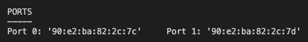
At the top of the manager display (pictured below), you can observe two (or more) port IDs and their associated MAC addresses. Use these ID mappings to complete the Port ID sections of the Topology Template.
Now that the Topology Template is complete, all commands within the PDF document should be populated. To complete our LB configuration, we must:
Specify the backend servers’ port information in server.conf
Define a static route in each of the backend servers to specify the correct gateway for which traffic will enter.
To specify the server information for the load balancer, go to
/examples/load_balancer/server.confand copy the information that is shown in the bottom left quadrant of your Topology Template. This includes the “LIST_SIZE 2” and the IP+MAC address of each port.To define the static routes, navigate to the two backend nodes (Server1 and Server2) and execute the respective commands shown on the bottom-center area of the Topology Template. This includes the
sudo ip route add *command for each server.
Running The Load Balancer
Since the ONVM environment is set, we can begin running the load balancer. In order to properly map IPs to HWAddresses, we must run the ARP NF. To do so, open a new terminal within the ONVM node; enter the
/examples/arp_responsedirectory and run the command shown at the top of the Topology Template labeled “Run Arp:”. Once properly running, the NF will appear as below: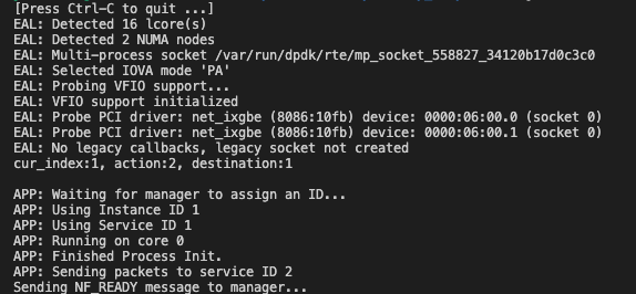
We can now run the load balancer. Note that the ARP NF and the LB NF can be started in any order, but both NFs must be active in order for the load balancer to handle traffic. To run the load balancer, navigate to the
/examples/load_balancerdirectory and run the command shown at the top of the Topology Template labeled “Run LB:”. The LB NF will appear as below:
To check that the ports have properly been applied to the load balancer, you may confirm that the listed MAC addresses and Port IDs are correctly associated under “Load balancer interfaces” (in the picture above).
Testing The Load Balancer with iPerf (recommended):
iPerf is a simple packet-generation tool which we may use to confirm that the load balancer is properly distributing traffic. To run iPerf, perform the following:
In the terminal of both backend servers, execute the command
iperf -s. This will start a TCP server on each of the backend nodes.Following, you may start the iPerf client on the client node using the command
iperf -c <X.X.X.X>where the IP to fill is the client-side port on the ONVM node.At this point, you should notice traffic being sent from the client and being received by one of the two servers. If you run the client multiple times, you should observe that the traffic is being distributed across each of the backend nodes evenly.
iPerf Client

iPerf Server
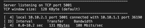
iPerf provides incremental throughput and bandwidth. Results can be seen below. Additional traffic information can be obtained by changing/adding command-line arguments, as discussed here. This page also provides instructions for running a UDP Client and Server, rather than TCP.
Testing The Load Balancer with Pktgen:
In accordance with the previous tutorial, we can use Pktgen to generate fake packets which will allow us to perform more throughput-intensive testing. Using the Pktgen tutorial, follow the directions regarding “Running Pktgen with 1 Port.” Ensure that Pktgen is running on the client node, and the indicated port in
/tools/Pktgen/openNetVM-Scripts/pktgen-config.luacorresponds to the client-side port on the main ONVM node (which is running the manager). For further detail, follow the instructions below:
In the following, we will refer to the client node as Node A and the ONVM node as Node B
On Node B, start the manager, the ARP NF, and the load balancer.
On Node A, ensure that the one port (which you intend to send packets through) is bound to the DPDK-compatible driver. Then, go to
/tools/Pktgen/openNetVM-Scripts/pktgen-config.luaand add the client-side port ID and Mac Address (from the ONVM node) into the script, as shown below.
In the same
/OpenNetVM-Scriptsdirectory, execute the command./run-pktgen.sh 1. This will begin Pktgen, and you can start the traffic by executingstart all.If Pktgen cannot successfully start, reference the installation guide for additional help.
Once Pktgen is running, you should be able to view the flow of traffic on the manager, as they are received on the client-side port and sent on the server-side port. If you would like to get further information, you can run the command
sudo tcpdump -i <IFACE>on each of the backend servers (where <IFACE> is the server’s interface name) to view all incoming traffic.Please note that generation of fake packets on Cloudlab often causes many packets to be dropped, making the use of Pktgen unideal in some circumstances.
Troubleshooting:
If you receive the error
connect failed: No route to hostwhen starting the iPerf client, it is possible that the ARP NF was unable to complete all of the necessary IP/HWAddress mappings. When running the ARP NF, please be sure that IPs are listed in the same order as the DPDK port numbers they correspond to. If this was not the issue, we can check whether the mappings are incomplete by executingarp -nin the command line of the client node. If the HWaddress resolves to(incomplete)(example shown below), then the MAC address must be mapped manually. Refer to the Topology Template to confirm the correct hardware address for the client-side ONVM port. Then, execute the commandsudo arp -s <X.X.X.X> <X:X:X:X:X>where the first input is the ONVM client-side port IP and the second input is the client-side port MAC address. Using the template above, the arguments would besudo arp -s 10.10.1.2 90:e2:ba:82:2c:7c. Additional manual mappings may also be needed on the backend nodes. The same process is applied, but the mapping will now correlate to the server-side ONVM port. Confirm that the HWaddress has now been added by runningarp -n, and proceed with running the iPerf client again.